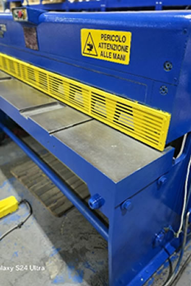
The windings are made as a concentric type and provide maximum through-fault withstand capability. This construction provides maximum strength and short-circuit withstand capability, increased predictability and lower hot-spot temperatures for loading and overloading.
Engineering Process
State-of-the-art design techniques are used to provide maximum impulse strength in the windings and to minimize voltage stresses. Special design consideration is also given to the line end discs to control voltage stress distribution.
- We use copper and aluminum conductors, depending on the transformer type and technical requirements.
- The conductors can be:
- Enamelled wires – for compact windings with reliable insulation.
- Paper‑insulated rectangular conductors – for higher current capacity and mechanical stability.
- Foil (copper or aluminum) – for high‑voltage windings, ensuring optimal current distribution and reduced losses.
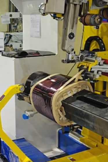
Synthesis Gradual layer winding
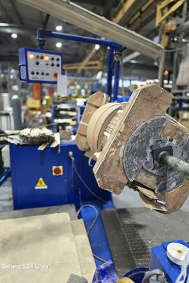
Winding machine
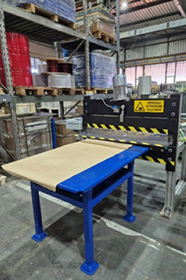
Paper cutting machine
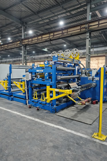
Foil Winding Machine
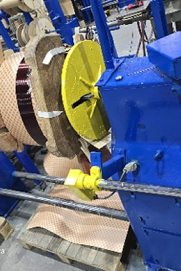
Winding machine
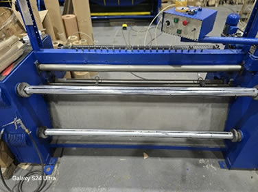
Paper slitting line
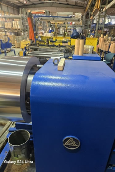
Foil Winding Machine